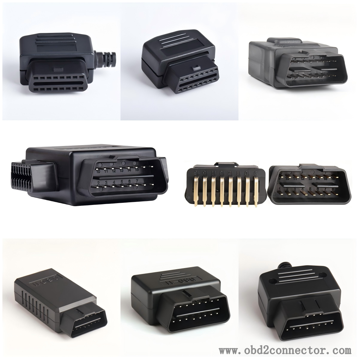
Deep analysis of the physical characteristics and structure of OBDII connectors
The OBDII connector is an indispensable diagnostic interface in modern automobiles, which enables technicians to easily access the vehicle's electronic control system for fault diagnosis, performance monitoring, and data collection.

1、 Appearance and dimensions of OBDII connectors
The OBDII connector is a standardized diagnostic interface that typically has a trapezoidal appearance with 16 pins distributed in a specific arrangement on the connector. The housing of the connector is usually made of durable plastic material, which has good insulation performance and protection level to prevent moisture, dust, and other pollutants from entering the interior of the connector.
The size of OBDII connectors is also standardized, ensuring that vehicles of different brands and models can use the same diagnostic tools and equipment. This standardized design not only improves the convenience of diagnosis, but also reduces maintenance costs, as technicians do not need to prepare different diagnostic interfaces for each vehicle model.
2、 Pin configuration and function of OBDII connector
Not all of the 16 pins of the OBDII connector are used for diagnostic communication. In fact, only some pins are assigned specific functions for transmitting diagnostic data, power, and grounding.
Pin 2 and 10: These two pins are typically used for communication of SAE J1850 PWM (Pulse Width Modulation) protocol. Pin 2 is Bus+(positive bus), pin 10 is Bus - (negative bus). This protocol is mainly used by Ford Motor Company.
Pin 6 and 14: These two pins are used for communication of ISO 15765 CAN (Controller Area Network) protocol. Pin 6 is CAN high, pin 14 is CAN low. The CAN protocol is a widely used network communication protocol that has advantages such as high speed, high reliability, and flexibility.
Pin 7: This pin is used for K-line communication of ISO 9141-2 and ISO 14230-4 (KWP2000) protocols. K-line is a half duplex serial communication line used for transmitting diagnostic data.
Pin 4 and 5: These two pins are typically used as ground to provide a stable voltage reference for the entire diagnostic system.
Pin 16: This pin is used to provide power (Battery Positive) and necessary electrical support for diagnostic tools.
Other pins (such as pins 1, 3, 8, 9, 11, 12, and 13) are usually not used by standard protocols and can be functionally defined by the vehicle manufacturer themselves.